-
Shop Parts
- Shop Accessories
- Shop Overland
-
Shop by Vehicle
![Select Vehicle]() Select Your Vehicle
Select Your Vehicle - Videos & Resources
Sign in to my account
ARB Compressor/Locker Kit Installation Instructions
Applies To:
Item: 9473
Fits: All
Specifications
| Motor Voltage | 12V |
| Current Draw | No load 9amp |
| Full load | 20amp |
| Pressure Switch | |
| Opens | 690 kPa (100psi) |
| Closes | 585 kPa (85psi) |
| Flow Rate | 30.0 lpm @ 0 kPa |
| 27.5 lpm @ 100 kPa | |
| 24.0 lpm @ 200 kPa | |
| 21.0 lpm @ 300 kPa | |
| 19.5 lpm @ 400 kPa | |
| 16.5 lpm @ 500 kPa | |
| 15.0 lpm @ 600 kPa | |
| 14.0 lpm @ 700 kPa | |
| Dimensions | |
| Length | 170mm |
| Height | 176mm |
| Width | 107mm excluding pressure switch |
| 170mm including pressure switch | |
| Weight | 3.8 kg |
| Features | Die cast aluminum tank |
| Extruded aluminum barrel | |
| Carbon impregnated Teflon piston rings | |
| Close-coupled motor | |
| Poppet valves | |
| Unitary construction | |
| Sintered steel counter weight | |
| Sintered bronze replaceable filter |
Notes
The above specification are based on an operating voltage of between 12 & 14 volts (i.e. the vehicle's engine must be running). The company reserves the right to adopt, without prior notice, specifications other than those set forth above. The ARB air compressor is designed to operate under normal conditions. Prolonged use over 45 minutes in elevated temperatures above 40C may result in damage. When used to inflate in these conditions we recommend it be allowed to cool down after a maximum running time of 45 minutes.
When the compressor is operating the Air Locker(s), or used to inflate in dusty conditions, the compressor will draw in dust. Ensure the air filter is cleaned after use in these conditions. Caution should also be observed when fording rivers to ensure the compressor is protected from ingesting water.
Locate position in vehicle where compressor is to be mounted and use backing plate to mark position of holes.
Hold compressor in position and insert four hex head screws through through holes. Fit backing plate over screws, then fit washers and nuts. Tighten. Rotate compressor to desired position and tighten clamp bolt.
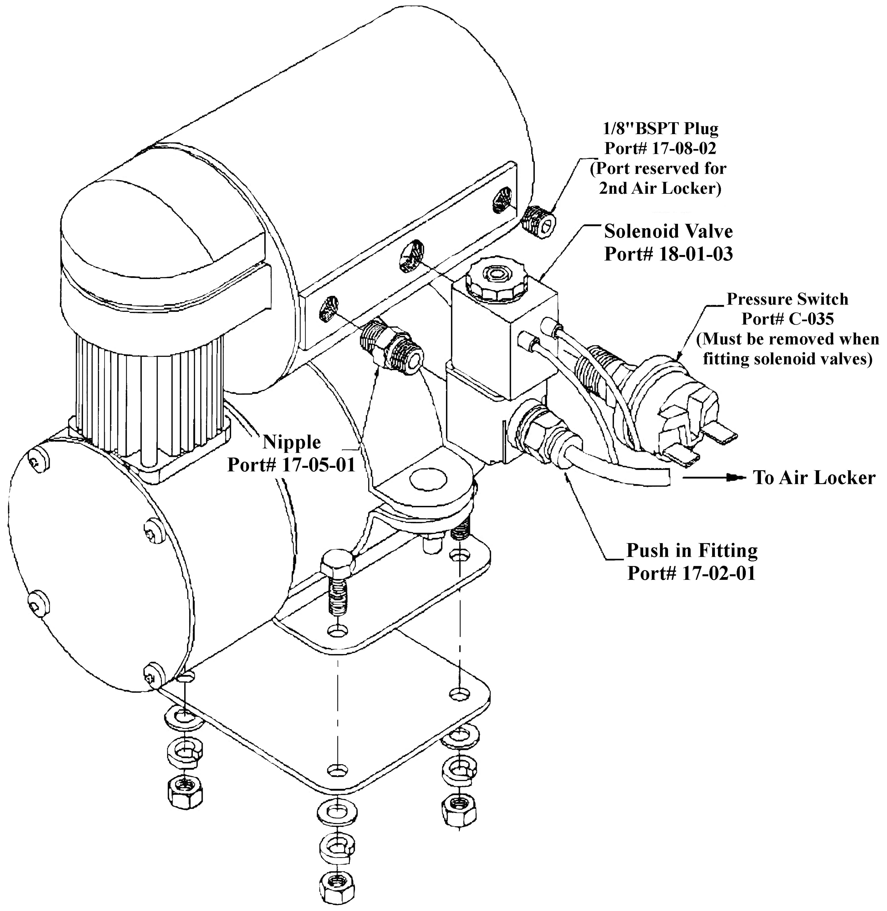
Screw nipple and solenoid valve (from Air Locker Kit) into spare 1/8" BSP port (remove plug first) using Loctite 569 or equivalent, then fit pressure switch as per diagram below. Connect loom and airline tube as per Air Locker instructions.
Note: If a second Air Locker is being installed the pressure switch must be temporarily removed to allow the solenoid valve to rotate.
1 2 
What Our Customers Are Saying


