-
Shop Parts
- Shop Accessories
- Shop Overland
-
Shop by Vehicle
![Select Vehicle]() Select Your Vehicle
Select Your Vehicle - Videos & Resources
Sign in to my account
Range Rover Sport (MY 2006 - 2009) & LR3 (MY 2005 - 2009) Coil Spring Conversion Kit
Applies To:
Item: L319SRK-A and L320SRK-A
Fits: Range Rover Sport | '06 - '09, LR3 | '05 - '09
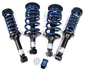
Kit # L319SRK-A shown
Included in Kit:
- 2 ea. L319SRK-FRNT (or L320SRK-FRNT)
- 2 ea. L319SRK-REAR (or L320SRK-REAR)
- 12 ea. M10x1.50mm Serrated Flange Nut
- 1 ea. 7982 EAS Re-Flash Device
Tools Needed:
- Diagnostic Computer (For depressurization of air spring - Optional)
- 21mm Wrench (Bottom Bolt Hex Head)
- 24mm Socket (Bottom Bolt Nut)
- Air Impact Wrench
- 15mm Wrench (Top Mount Nuts - 3 ea.)
- 12mm Wrench (To loosen the air supply nut)

Part I - Front & Rear Air Spring / Shock Removal
Part II - Front & Rear Coil Spring / Shock Installation
Part III - Installing the Air Suspension Configuration Device
Part I - Front & Rear Air Spring / Shock Removal
BACK TO TABLE OF CONTENTS
Removal of the Stock Front Air Struts
1. Raise and support the vehicle.
CAUTION: Do not work on or under a vehicle supported only by a jack. Always support the vehicle on safety stands.
2. Remove the tire.
3. If you have access to a Diagnostic Computer that is capable of depressurizing the air spring, you can do that now.
4. Remove the bottom bolt. (See Figure #1 & Figure #2)
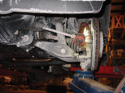
Figure 1
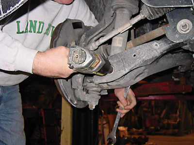
Figure 2
5. At this point the Shock Removal Instructions from Land Rover direct you to remove the plastic wheel well shroud from the vehicle. Our technical staff at Atlantic British has been able to remove the parts without removing the shroud. If you are having difficulty accessing the top mount nuts, you will need to remove this shroud.
6. Remove 3 top nuts supporting the weight of the assembly, so too much stress is not placed on the air supply line. (See Figures #3, #4, & #5)
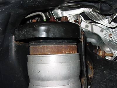
Figure 3
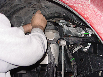
Figure 4
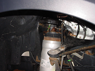
Figure 5
7. If you did not depressurize the air spring in step # 3 above, you can do it now. While continuing to support the weight of the Spring / Shock assembly, SLOWLY loosen the nut securing the air supply line to the air spring. As you loosen the nut, you will eventually hear the air begin to escape from the spring. Proceed with even more caution at this point letting the air escape slowly. It is dangerous to allow the pressure from the air spring to violently force the fitting out of place.
8. Maneuver shock assembly out from under vehicle.
9. Disconnect the electrical connectors from all four height sensors and wire tie them to prevent contact with any moving components.
Part II - Front & Rear Coil Spring / Shock Installation
BACK TO TABLE OF CONTENTS
1. Remove Brake Calipers to allow more room for installation of shock. (See Figures #6 & #7)
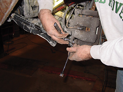
Figure 6
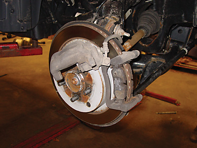
Figure 7
2. Carefully observe the pattern of the top mount studs on the Coil Spring / Shock assembly, and observe the corresponding pattern of the mounting on the upper bracket. (See Figure #8)
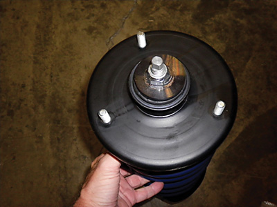
Figure 8
3. Maneuver the assembly into place and loosely secure with the 3 each M10x1.50mm Serrated Flange Nuts. Observe the alignment of the bottom mounting eye of the shock. If it is not aligned with the bracket, you will need to remove the assembly, compress the spring and adjust for the alignment. (See Figures #9 & #10)
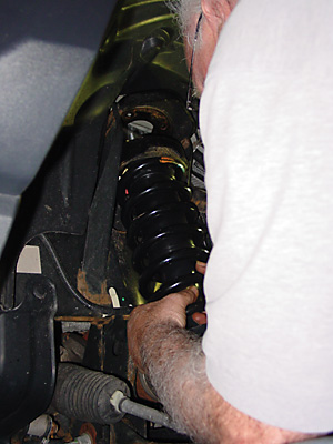
Figure 9
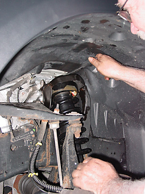
Figure 10
4. Align the bottom mounting ring with the bracket in the lower arm. You might need to move the arm up or down to get the holes to align. Slide the bolt into place and tighten the nut to 200 Nm (221 lb.ft.). (See Figures #11, #12, & #13)
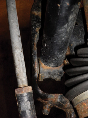
Figure 11
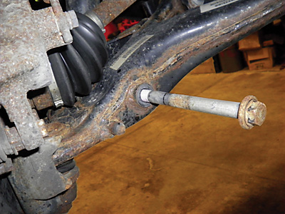
Figure 12
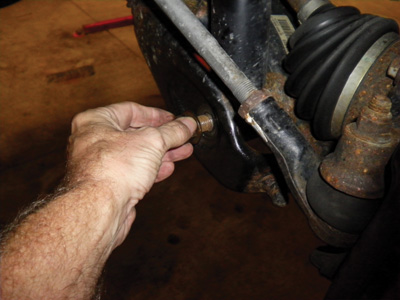
Figure 13
5. Tighten the 3 top mount nuts to 70 Nm (52 lb.ft.)
6. Reposition and install Brake Caliper.
7. Mount the tire.
Part III - Installing the Air Suspension Configuration Device
Item: 7982
For LR3 (MY '05-'09) & Range Rover Sport (MY '06-'09)
Function and Installation:
Requirement: When replacing a dynamic air spring suspension with a coil spring suspension, the EAS (Electronic Air Suspension) ECU (Electronic Control Unit) will generate error messages due to the lack of control of the coil spring suspension.
IMPORTANT! The device will automatically store the Vehicle Identification Number (VIN) of the first vehicle that it is connected to. It will then be permanently locked to that vehicle.
NOTE: The EAS ECU is located on the left side (driver) of the vehicle for the LR3 (L319) and Range Rover Sport (L320). It is located on the right side (passenger) on the Range Rover HSE (L322).
Before You Start:
- Clear all fault codes from all ECU’s.
- Disconnect vehicle battery.
- Unplug all vehicle ride height sensors.
Please Note: Battery should be reconnected only AFTER hard wire splice is completed.
Installing the Override Module:
Tools Needed:
- Flat Blade Screwdriver (or Panel Popper to remove Foot Rest Top)
- 10mm Socket with extension
- #15 Torx Driver
- Phillips Screwdriver
- Wire Citters
- Wire Strippers
Procedure:
Access to EAS ECU:
1. Remove the Foot Rest by first popping the cover off, then remove 2 ea. nuts. (See figure 1 & 2)
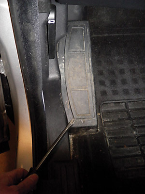
Figure #1.
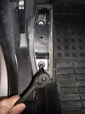
Figure #2.
2. With the Foot Rest out, you can remove the Left Side Panel by taking out the hood release lever (Torx Screw) and pulling the panel toward you. (See figure 3 & 4)
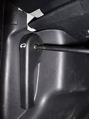
Figure #3.
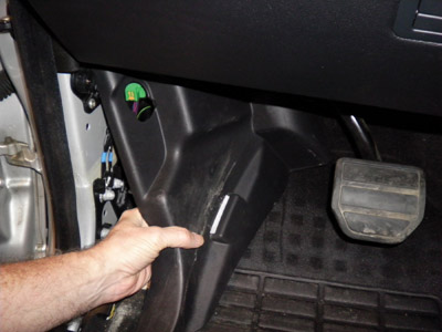
Figure #4.
3. Loosen the 2 screws securing the upper panel and drop it down. You don't need to remove it as long as you can secure it so that it is out of the way as you work on the EAS ECU wiring harness. (See figure 5)
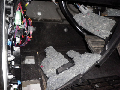
Figure #5.
4. Remove the panel just below the steering wheel by pulling it toward you. It will come right out as seen in this picture. (See figure 6)
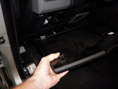
Figure #6.
5. Locate the EAS ECU. It will be mounted fairly high up on the left wall in the cavity that you have just exposed with the removal of the panels. (See figure 7)
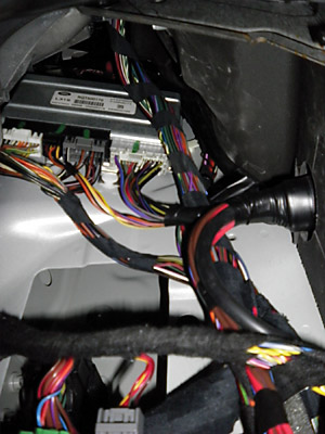
Figure #7.
6. Locate the mounting bolt at the top of the EAS ECU. It will be difficult to see, but you can feel it at the top of the ECU. Use the 10mm socket to remove the bolt. The ECU can then be pulled down by first pushing it up a bit to free it from the mounting "pegs" along the bottom of the unit. With the unit free of its mounting you can maneuver it down allowing access to the connectors and wiring harness. (See figure 8)
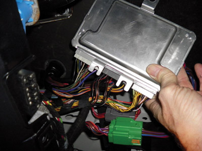
Figure #8.
7. Locate connector C0867 and unplug it from the ECU. (See figure 9)
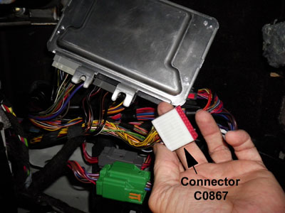
Figure #9.
8. Examine the backside of the connector and identify the 2 Data wires. The wires are in position 16 and 19 of the connector. They will be twisted together. (See figure 10, 11, 12)
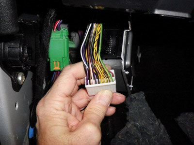
Figure #10.
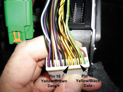
Figure #11.
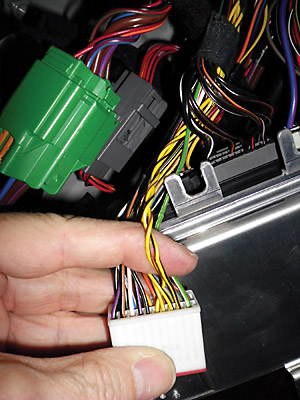
Figure #12.
9. Cut the 2 data wires. Be sure to double (and triple) check the wires before cutting. As you might imagine, cutting the wrong wires will cause you much difficulty as you proceed with this installation. (See figure 13)
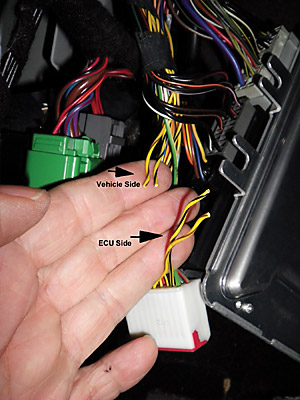
Figure #13.
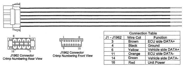
10. Strip the insulation from each end of the 2 Data wires you just cut (4 strips total) and strip all 6 wires on the Filter Module Wiring Harness (supplied with the 7982 module) by 5/16 inch. (See figure 14)
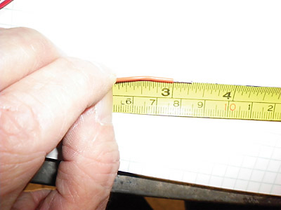
Figure #14.
11. Using the Posi-Lock wire splices connect the Data Wires to the Filter Module Wiring Harness as follows:
NOTE: It is VERY important that you take care to get the proper wires spliced together.
Vehicle Wires |
Filter Module Wiring Harness |
Data +, Yellow/Brown, ECU Side |
Brown |
Data +, Yellow/Brown, Vehicle Side |
Yellow |
Data -, Yellow/Black, ECU Side |
Orange |
Data -, Yellow/Black, Vehicle Side |
Green |
Addendum A.
12. After the Data Wires are spliced, your harness should look like this. (See figure 15)
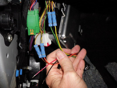
Figure #15.
13. Locate the positive power wire on C0867. It will be in position 20 (next to the Yellow/Black wire you just spliced) (See figure 16)
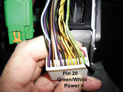
Figure #16.
14. Using the smaller (Red / Brown) Posi-Tap connect the Red wire from the Filter Wiring Harness to the Green/White wire. You do NOT need to cut the wire, we are just tapping into the power on this wire. (See figures 17, 18)
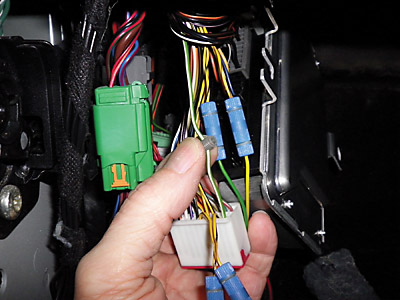
Figure #17.
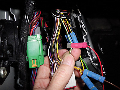
Figure #18.
15. Locate connector C2321, and unplug it from the ECU. (See figure 19)
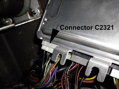
Figure #19.
16. Locate the Black wire in position 24 of C2321 and using the larger Black Posi-Tap connect the Black wire from the Filter Wiring Harness to this wire. Just like with the power wire in step # 14, we are NOT cutting this wire, just splicing. (See figures 20, 21, 22)
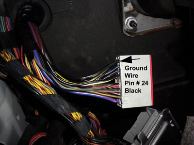
Figure #20.
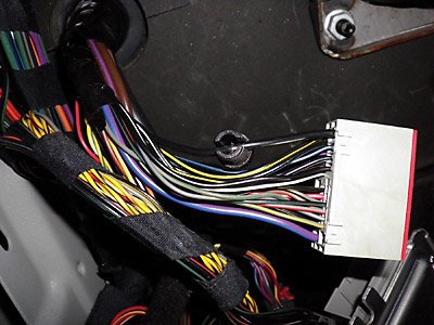
Figure #21.
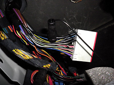
Figure #22.
17. Reinstall all of the panels, and the Foot Rest.
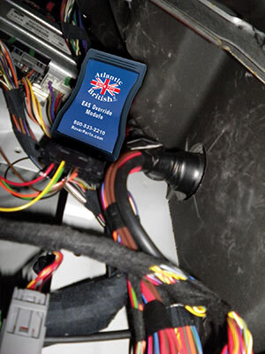
Figure #23.
Part IV - Troubleshooting
If you still have suspension errors after install, most often the problem is a related missed step. Performing these steps in order will often solve the issue:
1. Clear all fault codes from ALL ECU’s (not just EAS fault codes).
2. Disconnect the battery.
3. Unplug the four ride height sensors and make sure they are taped-off.
4. Reconnect battery.
BACK TO TABLE OF CONTENTSWhat Our Customers Are Saying


